Johann Borenstein's D.Sc. Thesis "Development of a Nursing Robot System" included the development of a mobile robot system (the Nursing Robot) to help physically handicapped people. Completed in 1986, the Nursing Robot was one of the first fully functioning mobile robots equipped with a manipulator arm. Also integrated were seven different sensor systems. The system was controlled by four networked onboard Sinclair Spectrum Computers (based on the then popular Z80 processor) and an off-board IBM-PC (8086 processor).
This document describes the features of the mobile Nursing Robot System developed at the Technion. The Nursing Robot System comprises three major components: a self-propelled vehicle, a robotic arm mounted on it, and a communications post (workstation) next to the disabled person's bed. Onboard the mobile robot low-cost microcomputers are interconnected as a hierarchical network, in order to control a variety of activities: Sensor data processing, motion control, path-planning, communication, and others. The vehicle can move autonomously in a room with unexpected obstacles.
FORTH has been used as the programming language, because of its compactness, speed, and extendibility. The paper discusses the hierarchical structure of the system with special attendance to the hierarchical software of the motion module.
Work now in progress at the Technion's Department of Mechanical Engineering aims at the development of an autonomous mobile robot system, capable of performing various tasks for the physically disabled. Such a device, is hoped, will return a measure of independence to many bedridden persons, as well as reducing the number of those in need of hospitalization and constant attendance.
The robot can perform simple services, such as fetching a glass of water, operating electrical appliances or replacing a cassette in a video-recorder. The system contains a vehicle, a five degrees-of-freedom (DOF) robotic arm mounted on the vehicle, and a computerized post next to the disabled person's bed.
In order to interact intelligently with its environment, the robot utilizes the following sensors:
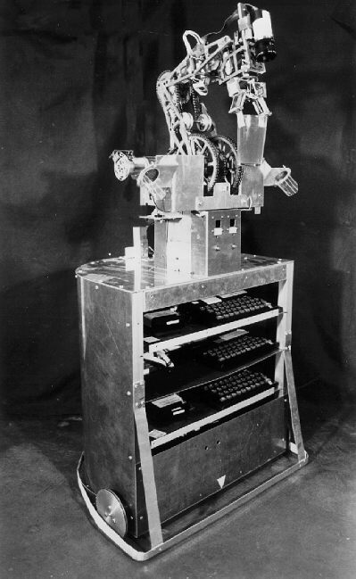
A prototype of the nursing robot vehicle is shown in Fig.1. It comprises two main components: The mobile platform which houses the computers and the electronic hardware, and a commercially available manipulator, to which the two ultrasonic transceivers and the light detecting sensor are attached. Fig. 1 also shows the specially devised multipurpose gripper with its integrated 3 DOF-force sensor, as well as the floor level bumper with the Micro switches.
This document outlines the hierarchical structure of the computer system and describes a case study at the end. The choice of micro-computers is explained and the advantages of FORTH as a programming and development language will be discussed.
Figure 2 {note: Fig. 2 not included in this document} shows the hierarchical computer structure of the system which consists of three distinct levels of computation. The lowest level comprises three microcomputer controllers that directly interact with electronic hardware:
All three controllers are interfaced with each other as well as with the medium level with the help of a NETWORK, which is a standard feature in the microcomputers used in this application (Z80A-based SINCLAIR SPECTRUM {note in 1995: These little gems cost $350, including 64 Kbyte RAM, rubber-keyboard, composite video driver, network adapter, and hybrid endless tape drive with 85 Kbyte capacity and 5 sec. average seek time}. The NETWORK is especially attractive during the development phase of the system, since it is readily expandable to 64 computers without any additions of either hardware or software. Therefore, more features may be added to the system even in an advanced state of the development.
The scheduler computer is at the medium hierarchical level. It receives commands from the highest level and relates these commands, via the NETWORK, to the respective controllers (or vice versa). Presently, data are transferred between the scheduler (onboard the robot) and the high level computer (fixed within the bedside post) by means of a RS232 cable. A wireless data link, such as radio or infrared, could be employed, for a commercial system.
At the highest level of the system (this computer is an off-board IBM PC 8086), artificial intelligence algorithms break down spoken commands into adequate series of actions. Relevant sensory information is processed here, global-path planning (for the platform as well as for the robotic arm) is performed while concurrently monitoring the voice recognition input.
Except for the highest level computer, all computers in this application are SINCLAIR SPECTRUM microcomputers. This unconventional choice has some distinct advantages over others in view of the following special circumstances:
After establishing the advantages of the use of commercially available microcomputers for this project, another important consideration was the weight and size of the computer, several of which were to be installed onboard the mobile robot.
SINCLAIR SPECTRUM microcomputers were found to meet the above requirements as well as to offer some additional desirable features, which are listed below:
1. The computer is small (240mm x 150mm x 30mm) and weighs less than most other microcomputers (570gr). Therefore, the four required computers can easily be installed (even with their own keyboard and housing) onboard the vehicle {note: the camera-computer was not installed at the end of the project in 1986}.
2. With a computer installed and connected to all its peripheral devices, it is still possible to:
a. program and operate the computer with its keyboard,
b. load and save programs with its attached microdrive, and
c. view programs or results on an attached monitor.
These facilities largely simplify the development and especially the debugging of programs allowing for a totally interactive process at any time - even when the robot is "on route". The interactive character is further enhanced by the use of FORTH, as will be explained later.
3. After FORTH has been loaded into the computer, there are still 30K of RAM available to the user. In view of the extreme compactness of compiled FORTH, this has been found sufficient for our application. Also, the operating system is resident in ROM and available at any time.
The programming language for all three levels is FORTH, a relatively new, procedure based language [2] of increasing popularity [3,4], which lends itself to this application for several reasons:
One part of the motion module has been depicted in Fig.3 in order to demonstrate the interleaving hierarchical software and hardware structure.
At the lowest hierarchical level, the hardware level, electronic devices such as Digital to Analog Converters (DACs), counters etc. are interfaced with the motion controller, mainly through input/output ports of the computer. At the lowest software level, procedures interact with the respective ports by sending or receiving data. These "driver" procedures are normally designed in such a way that replacing a certain electronic device ( e.g., replacing the DACs and power amplifiers with a Pulse Width Modulator, to drive the motors) would only require a change in the driver procedure in question, without having any effect on the higher level procedures.
Data to be input or output by the software drivers is calculated at the next level (e.g., the block marked CONTROLLER in Fig. 3 {Note: Fig. 3 not included in this document}. This is a digital cross-coupled control algorithm, which has been thoroughly analyzed in a previous paper [8]). The block marked SEQUENCER controls the four motion phases: a) acceleration, b) constant velocity, c) deceleration and d) overshoot correction, which are employed for either rotational or translational motion of the vehicle. Also, the SEQUENCER will abort a motion sequence upon receiving an alarm from the sonar sensors (indicating detection of an obstacle). A detailed description of the obstacle avoidance algorithm is given in Paper 03.
At the next level, motion primitives such as FORWARD or RIGHT allow the operator to drive the vehicle on a straight line or to rotate the vehicle on the spot. Alternatively, the high-level directive MOVE will calculate the required amount of rotation and translation to reach a certain location in the room and call the respective motion primitives to perform that motion.
The block above, designated SCHEDULER, is implemented in the scheduler computer. Its task is to switch on the ultrasonic scanner (implemented in the sensor controller), then to pass on the required task coordinates to the block MOVE, switch off the ultrasonic scanner upon completion of the motion and to pass on a status report to the highest level computer. If invoked directly by the operator at this level, SCHEDULER will move the vehicle to the desired task location, but will stop if an obstacle was detected.
The PATH-PLANNER is implemented in the highest level computer and is in fact an elaborate artificial intelligence program [9] designed to find an optimal path between the present location of the robot and a desired task location, in a room filled with known obstacles. The PATH-PLANNER outputs a list of intermediate coordinates to the SCHEDULER, and then awaits the status report. If an unknown obstacle was detected, the PATH-PLANNER initiates an ultrasonic scan of the obstacle, and adds the resulting new obstacle data to its internal world model. Subsequently, the PATH-PLANNER recalculates an optimal route, until the desired location is reached.
The very highest level of the system comprises the TASK-SEQUENCER. This is an artificial intelligence program which decomposes a natural language command into an appropriate series of actions, including motions of the vehicle and motions of the robot-arm. This level is called the Task level, since the operator only specifies a task (e.g., "Bring glass from table"), without specifying the required steps to perform this task. The actual steps might be different for the same command, since they depend on the room obstacles and the location of the vehicle at the time the command is given.
On its way the Nursing robot can detect obstacles with its two front-and-downward-facing sonars. Upon detection, the robot stops and scans the obstacle horizontally, by means of its Rhino manipulator arm onto which the sonars were mounted. The algorithm detects edges of the obstacles and updates the internal world model with the information. An optimization algorithm then recomputes an optimal path around the obstacle and toward its next intermediate target.
The Nursing robot is capable of visiting a list of predefined target coordinates. An advanced version of the Traveling Salesman Algorithm (see Paper 08) computes not only an optimal tour among its targets, but it does also take into account the robot's need to return to its home position after 20 or so meters of travel to do an absolute position update. Dead-reckoning accuracy is modeled as a resource the robot runs out of over time (or distance). The optimizer also takes into account the fact that certain locations must be visited immediately prior to other locations, for example if the robot needs to fetch a book and bring it to another location while holding the book in its gripper, then visiting other (potentially closer locations) would not make much sense, until the book was delivered and released at the book's target location. The algorithm developed for this task ran on the IBM PC and was also programmed in FORTH.
A hierarchical multiprocessor and multisensor robotic system of considerable complexity has been designed, built and tested. In order to implement this system, a highly structured and modular software and hardware design has been used. The unconventional choice of microcomputers together with the interactive facility of FORTH have been found to be of utmost value for development and debugging of the system.
{This section added in 1995:} To give the reader a sense of the typical challenges that faced the robotics experimentalist in 1985/86, here are a few anecdotes:
1) Borenstein, J. and Koren, Y.: A Mobile Platform For Nursing Robots". IEEE Transactions on Industrial Electronics, May 1985, pp.158-165.
2) Brodie, L.: "Starting FORTH". Prentice Hall, Inc., Englewood Cliffs, 1981.
3) The Journal of FORTH Applications and Research, Vol. 1, Issue 1, September 1983.
4) Michaloski, J. L. and Warsaw, B. A.: "A Robot Control System Based on FORTH". Robotics Engineering, May 1986, pp. 22-26.
5) Borenstein, J.: "Fast Fixed Point Trig by Derivation". FORTH DIMENSIONS, May/June 1986, pp. 14-19.
6) Yoerger, D. R., Peterson, P. and Buharali, A. :"Control System Implementation Using FORTH". ASME 83-WA/DSC-28.
7) Lecky, J.E.: "FORTH For Computer Vision in Industrial Applications". Robotics AGE, 1985, pp. 25-28.
8) Borenstein, J. and Koren, Y.: "Motion Control Analysis of A Mobile Robot". Submitted for publication in: ASME Journal of Dynamics, Measurement and Control.
9) Borenstein, J. and Koren, Y.: "Optimal Path Algorithms For Autonomous Vehicles". Paper presented at the 18th CIRP Manufacturing Systems Seminar, June 5-6, 1986, Stuttgart.